ATTENTION!: THIS IS A CD, NOT A PHYSICAL/PAPER BOOK!!!
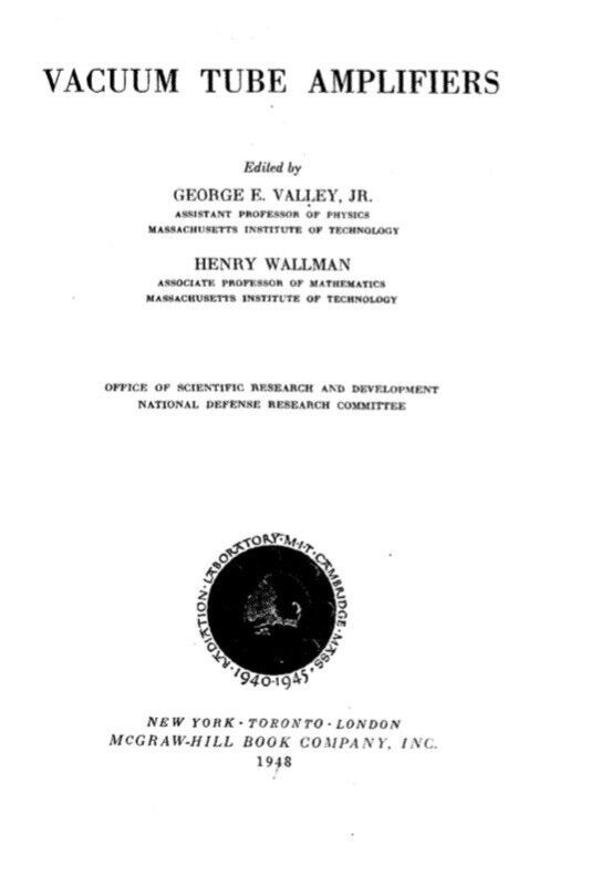
Vacuum Tube Amplifiers by George E. Valley and Henry Wallman 1948 PDF on CD
CD Contents:
Vacuum Tube Amplifiers by George E. Valley and Henry Wallman (1948): 761 pages
Format: PDF IN ZIP, Language: English
"The tremendous research and development effort that went into the
development of radar and related techniques during World War II
resulted not only in hundreds of radar sets for military (and some for
possible peacetime) use but also in a great body of information and new
techniques in the electronics and high-frequency fields. Because this
basic material may be of great value to science and engineering, it seemed
most important to publish it as soon as security permitted."
Table of contents of the book on the CD:
Chap. 1. LINEAR-CIRCUIT ANALYSIS AND TRANSIENT RESPONSE
1-1. Introduction
1-2. The Basic Properties of Linear Networks
1-3. The Integro-differential Equations of the Linear Network
1-4. The Theory of the Laplace Transform
1-5. The Use of the £-transform in the Solution of Network Problems
1-6. General Solution of the Network Equations
1-7. The Transform Network
1-8. The Steady-state Response of the General Linear Network
1-9. The Fourier Transform Method
1-10. Summary of the Use of £-transform Theory in Network Problems
1-11. Examples of Use of £-transform Theory to Solve Practical Net-
work Problems
Chap. 2. HIGH-FIDELITY PULSE AMPLIFIERS
2-1. Introduction
2-2. Leading Edge of Pulse; Rise Time and Overshoot
2-3. Flat Top of Pulse
2-4. Inverse Feedback
2-5. Gain Control of Pulse Amplifiers
2-6. D-c Restoration
2-7. Limiting Amplifiers
2-8. The Mixing of Multiple Input Signals
2-9. Electronic Switching of Pulse Amplifiers
2-10. Output Stages
2-11. Examples
Chap. 3. PULSE AMPLIFIERS OF LARGE DYNAMIC RANGE
3-1. Introduction
3-2. Theory of Overshoots
3-3. Circuit Design for Minimum Overshoot
3-4. Design Considerations
3-5. Small Amplifiers
3-6. Examples
Chap. 4. SYNCHRONOUS AND STAGGERED SINGLE-TUNED HIGH-
FREQUENCY BANDPASS AMPLIFIERS
4-1. Introduction
4-2. One Single-tuned Circuit
4-3. Amplifier Figures of Merit
4-4. Cascaded Synchronous Single-tuned Circuits
4-5. Example of a Synchronous Single-tuned Amplifier
4-6. Staggered n-uples. Arithmetic Symmetry
4-7. Staggered n-uples. Geometric Symmetry
4-8. Flat-staggered Pairs, in Detail
4-9. Flat-staggered Triples, in Detail
4-10. Gain Control of Stagger-tuned Amplifiers
4-11. Examples of Stagger-tuned Amplifiers
Chap. 5. DOUBLE-TUNED CIRCUITS
5-1. Introduction
5-2. The General High-Q Case
5-3. The High-Q, Equal-Q Case
5-4. The High-Q Case When One of the Q's Is Infinite
5-5. The Transitionally Coupled Low-Q Case
5-6. Stagger-damped Double-tuned Circuits
5-7. Construction and Examples
Chap. 6. HIGH-FREQUENCY FEEDBACK AMPLIFIERS
6-1. Introduction
6-2. Analysis of the General Chain
6-3. The Inverse-feedback Pair
6-4. Synthesis of a Feedback Chain
6-5. Miscellaneous Properties of Inverse-feedback Chains and Pairs
6-6. Practical Considerations in Feedback-amplifier Design
6-7. More Complicated Feedback Amplifiers
6-8. Practical Examples
Chap. 7. BANDPASS AMPLIFIERS: PULSE RESPONSE AND GENERAL
CONSIDERATIONS
Pulse Response
7-1. Response of Bandpass Amplifier to Carrier-frequency Pulse
7-2. One-pole Networks
7-3. Two-pole Networks
7-4. Maximally Flat Three-pole Networks
7-5. Maximally Flat n-pole Networks
7-6. Overstaggered Circuits
General Considerations
7-7. Gain-bandwidth Factor
7-8. Gain Control
7-9. Gain Variability
7-10. Capacity Variability
7-11. Pretuned Coils
7-12. Comparison of Amplifier Types
Chap. 8. AMPLIFIER MEASUREMENT AND TESTING
8-1. Swept-frequency Signal Generators
8-2. Direct and Carrier-frequency Pulse Generators
8-3. Miscellaneous Testing Equipment
8-4. Measurement and Alignment of Bandpass Amplifiers
8-5. Undesired Feedback Effects (Regeneration) in Bandpass Amplifiers
8-6. Pulse Response
8-7. Overload and "Blackout" Effects
8-8. Measurement of Gain and Determination of Amplifier Law
Chap. 9. LOW-FREQUENCY AMPLIFIERS WITH STABILIZED GAIN
9-1. Problems Characteristic of Computer Amplifiers
9-2. Analysis of Types of Feedback
9-3. The Stability Problem
Sample Designs of Computer Amplifiers
9-4. Single-stage Drivers
9-5. Driver with Push-pull Output Stage and Regeneration within the Loop
Two-stage Driver for Inductive Load without Transformer Output
9-6. General Considerations
9-7. Design of the Output Stage
9-8. Design of Pentode Stage
9-9. Constancy of Gain with Respect to Circuit Parameters
9-10. Stability against Oscillation
Three-stage Amplifier for Resistive Load
9-11. General Considerations
9-12. Design of Individual Stages
9-13. Stability against Low-frequency Oscillation
9-14. Stabilization against High-frequency Oscillation
9-15. Experimental Checks and Completion of the Design
Chap. 10. LOW-FREQUENCY FEEDBACK AMPLIFIERS
10-1. Frequency-selective Networks
10-2. Frequency-selective Amplifiers
10-3. The Design of Frequency-selective Amplifiers
Chap. 11. DIRECT-COUPLED AMPLIFIERS
Introduction
11-1. Applications of Direct-coupled Amplifiers
11-2. Problems Peculiar to Direct-coupled Amplifiers
Special Aspects and Effects of Vacuum-tube Properties
11-3. Variability of Vacuum-tube Characteristics
11-4. Vacuum-tube Characteristics at Low Currents
11-5. Grid Current
11-6. The Effect of Heater- voltage Variation
Design Principles
11-7. Single-ended Triode Amplifiers
11-8. Single-ended Pentode Amplifiers
11-9. Cascode and Other Series Amplifiers
11-10. Differential Amplifiers
11-11. Output Circuits
11-12. Cancellation of Effect of Heater-voltage Variation
11-13. The Use of Feedback in D-c Amplifiers
Examples of Special-purpose Amplifiers
11-14. Current-output Amplifiers
11-15. Voltage-output Amplifiers
11-16. A Galvanometer-photoelectric Tube Feedback Amplifier
11-17. D-c Amplifier Analysis
Chap. 12. AMPLIFIER SENSITIVITY
12-1. Introduction
12-2. Thermal Noise
12-3. Shot Noise
12-4. The Logical Distinction between Thermal Noise and Shot Noise
12-5. Other Types of Tube Noise
12-6. Other Types of Input-circuit Noise
12-7. Amplifier Sensitivity: Definition and Theoretical Discussion of Noise Figure, Available Power Gain, and Noise Temperature
12-8. Amplifier Sensitivity : Methods of Improvement by the Suppression of Tube Noise
Chap. 13. MINIMAL NOISE CIRCUITS
13-1. Introduction
13-2. Basic Noise-figure Considerations
13-3. The Determination of the Noise Figure, Power Gain, and Other
Characteristics of the First Stage
13-4. The Equivalent Noise Resistance of Practical Tubes
13-5. The First-stage Noise Figure
13-6. The Optimum Source Admittance
13-7. Variation of Noise Figure with Source Conductance and with
Frequency
13-8. Comparison of Alternative Tube Configurations
13-9. Noise Figures of Single-triode Input Circuits
13-10. Double-triode Input Circuits
13-11. General Considerations of the Effect of Feedback on Noise Figure
13-12. Miscellaneous Types of Feedback and Their Effect on Noise
Figure
13-13. The Correlation between the Induced Grid-noise and the Shot-noise Currents
13-14. Input Coupling Networks
13-15. Example of Alternative Designs of Input Coupling Network
Chap. 14. MEASUREMENT OF NOISE FIGURE
14-1. Introduction
14-2. Discussion of Available Power
14-3. Measurement of Noise Figure with Unmodulated Signal Generators. The Relation of Noise Figure to Other Quantities That Express the "Noisiness" of an Amplifier Noise Generators
14-4. General Discussion
14-5. Theory of Noise Generators Using Temperature-limited Diodes
14-6. Construction of Diode Noise Generators
14-7. Crystal Noise Generators
Measurement op Amplifier Output Power
14-8. Attenuator and Postamplifier
14-9. Method Employing Gain-control or Uncalibrated Attenuator
14-10. Crystal and Diode Rectifiers
14-11. Bolometers
14-12. Thermocouple Meters
Special Topics
14-13. Effect of the Gain Control
14-14. Correction for Temperature
14-15. Noise Figure of an Amplifier with Push-pull Input Connections
14-16. Measurement of Noise Figure of Superheterodyne Radio Receiver with Image Response
APPENDIX A. REALIZABILITY OF FILTERS
A-l. The Paley- Wiener Criterion
A-2. Examples
A-3. The Practical Meaning of the Paley- Wiener Criterion
APPENDIX B. CALCULATION OF LOAD-TUNING CONDENSER
APPENDIX C. DRIFT OF VACUUM-TUBE CHARACTERISTICS
UNDER CONSTANT APPLIED POTENTIALS
INDEX
COMPUTER REQUIREMENTS:
This old book on CD on PDF in ZIP format after copy it to the computer or put it to the device will work on all PC, MAC Computers, tablets and mobile phones. The softwares needed are adobe reader/adobe reader app and WinZip program which in most cases are already loaded onto your computer/device, if not can be downloaded for free.
It will be shipped by UPS/Air mail as a CD and money back guarantee!
Windows and Mac compatable
Important! Non US buyers please be sure that your State/Province/Region element is filled by you either in your paypal account Profile and settings/Address section or in your eBlueJay account Settings/Address section when you make order because this is necessary in order that the order processing can be a little bit quicker! Thank you for your cooperation! Ringostarn
00533
Payment Methods


Shipping
UPS, FREE Shipping
Payment Policy
I accept paypal and credit cards.
Shipping Policy
Shipping is FREE. It will be shipped in 6 business days by UPS from Sparks, NV, 89434, USA. I ship only to the USA. Tracking number will be added to the order. Please check the tracking number at www.ups.com! Thank you, Ringostarn
If you prefer a Download, please make a note with your payment!
Download means No waiting for the CD/DVD to arrive in the mail!
Here you can buy the downloaded item on a safest place: (Click here or copy paste in the browser the link under!)
Link:
https://www.etsy.com/shop/Ringostarn
Return/Exchange Policy
No returns
Please Login or Register first before asking a question.
